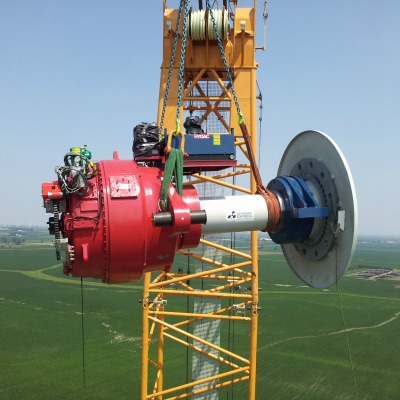
 Repairing or replacing a failed wind turbine gearbox is an extremely expensive undertaking. Gearbox failures are one of the largest sources of unplanned maintenance costs in the wind industry. When a failure occurs, it is important to correctly identify the failure mode so that the appropriate actions can be taken to reduce the likelihood of a reoccurrence of the same type of failure.
Gearbox failures can be caused by fundamental design issues, manufacturing defects, deficiencies in the lubricant or lubrication system, excessive time at standstill, high loading, and many other reasons. A correct failure mode diagnosis is the first step in identifying the actions that can be taken to prevent additional failures. Five of the most common gear and bearing failure modes, along with tips on identification and potential means of prevention, are provided below.
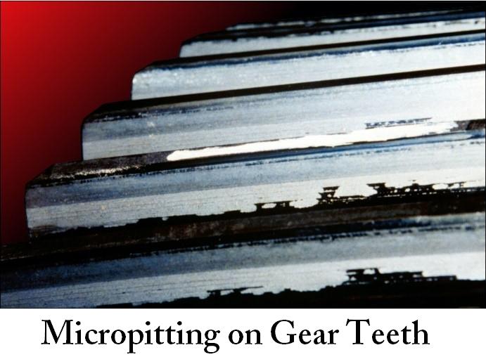
Micropitting can affect both gears and bearings, and failures due to micropitting are very common in wind turbine gearboxes. Micropitting occurs when the lubricant film between contacting surfaces is not thick enough and the surfaces have high amounts of sliding action. Micropitting results in a frosted or matte finish surface in affected areas, as seen in the figure above. Micropitting-related failures can be prevented by changing lubricant type or by reducing component surface roughness.
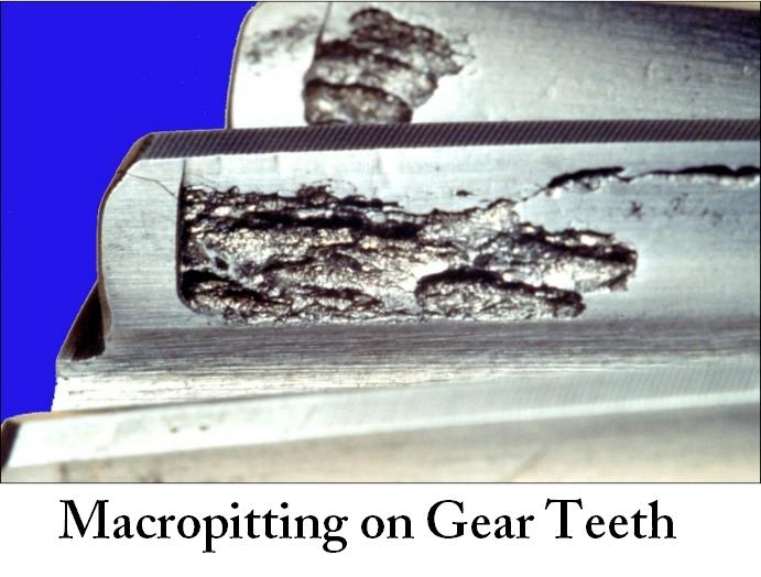 Macropitting can also affect both gears and bearings. Macropitting occurs when the contact stress in the gear or bearing exceeds the fatigue strength of the material. Wind turbine gears and bearings are typically designed for a 20-year service life, and macropitting that occurs before the end of the design life is an indication that one or more design assumptions, such as contact stress, material properties, lubricant condition or applied load, were not met. Macropitting results in craters on the gear tooth or bearing ring (or roller) surface. Beach marks due to the presence of corrosion and lubricant in the crack are sometimes present and indicate a fatigue progression process. Macropitting failures can be prevented by reducing loads, improving gear and bearing profiles to reduce stress, using cleaner steel, or increasing material strength, through alloy selection or a heat treatment process.
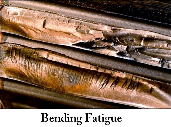
Bending fatigue is a failure mode that affects gear teeth. Bending fatigue failures occur when the stress at the root of the gear tooth exceeds the capability of the gear material. This can be due to excessive loads, incorrect heat treatment, inclusions in the steel or a notch in the root of the tooth. The appearance of the fracture surface will vary depending on whether the failure was high or low cycle fatigue. Features such as ratchet marks are occasionally present and indicate multiple crack origins. Bending fatigue failures can be prevented by decreasing load, increasing gear material strength or optimizing the gear root fillet geometry.
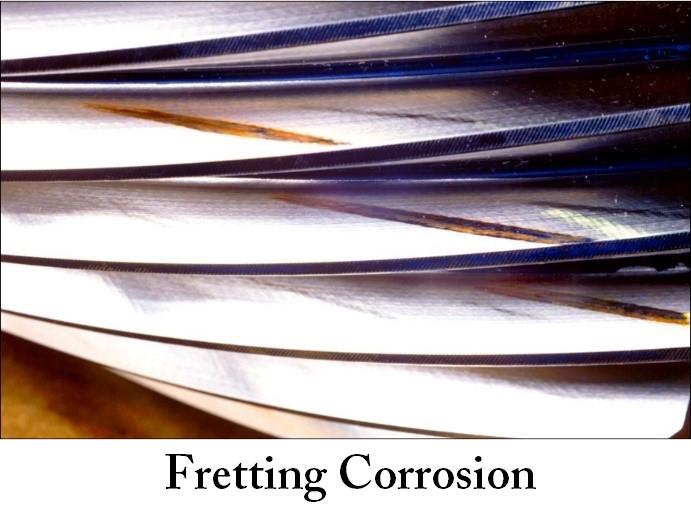 Fretting corrosion can affect gears and bearings. It is a surface-wear phenomenon that occurs when two contacting surfaces have small oscillating relative motions, with no lubricant film between the surfaces. It often occurs in wind turbine gearboxes due to transportation or to spending extended periods of time with no rotation. Fretting corrosion can be identified by the presence of ruts along the lines of contact, along with the presence of reddish brown or black wear debris. Fretting corrosion can be prevented by minimizing the amount of time that a gearbox spends without rotating or by improving transportation conditions, depending on the cause of the fretting corrosion.
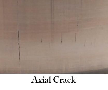
Axial cracking is a phenomenon that occurs in bearings, almost always on the bearing inner ring. Failures of this type have become very common in wind turbine gearboxes and were the subject of an article in the June 2013 issue of North American Windpower. The cracks develop in the axial direction, perpendicular to the direction of rolling. Axial crack failures are most likely to occur in through-hardened bearings. Axial crack failures can be prevented by using case carburized bearings, ensuring that the appropriate amount of retained austenite is present, applying a black oxide coating, and ensuring the correct level of interference fit exists between the bearing inner ring and the shaft on which it is mounted.
The wind turbine gearbox failure modes described in this article are some of the most common, but there are many others. They include case-core separation, plastic deformation, scuffing, polishing, adhesion, abrasion, subcase fatigue, erosion, electric discharge, cavitation, corrosion, and several additional forms of cracking. Regardless of the failure mode type, however, proper and prompt identification is key to preventing a reoccurrence of any gearbox failure.
Rob Budny is president and principal engineer at RBB Engineering, a Petaluma, Calif.-based consultancy. He has also co-developed gearboxfailure.com, an educational resource that contains a comprehensive listing of gear and bearing failure modes, with GEARTECH. Budny can be reached at (805) 280-9044 or rob@rbbengineering.com.
The first four images in this article are courtesy of GEARTECH, and the final image is courtesy of RBB Engineering. The cover photo of a gearbox on a crane is courtesy of Gearbox Express.


