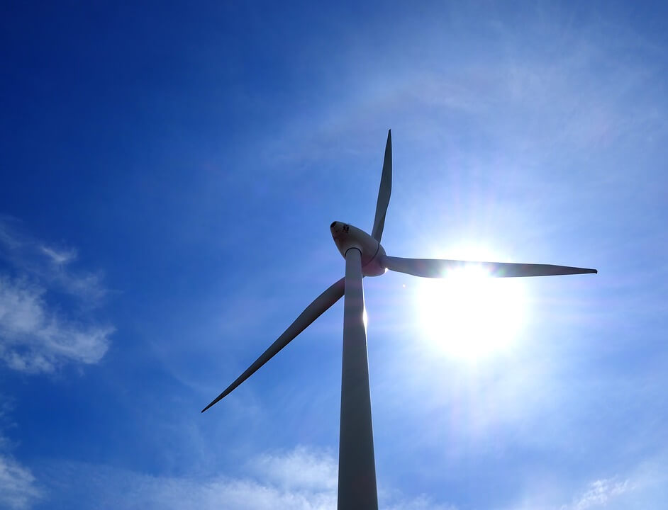
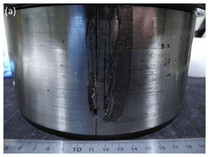
White etching cracks (WECs), also known as axial cracks, remain a primary cause of gearbox bearing failures in wind turbines, causing major disruptions to wind farms anytime a damaged bearing must be taken out of service (see Figure 1). These cracks typically occur within 5% to 10% of the bearing’s predicted life, and despite extensive research by the world’s leading bearing makers, universities and government agencies, the exact cause of the issue remains a moving target subject to a combination of factors, including dynamic stresses, frictional heat and lubrication composition, making cracking difficult to predict.
What is known is that carburized bearings offer a significant improvement in preventing the propagation of WECs compared to conventional through-hardened bearings. Recent testing by The Timken Co. in cooperation with the Applied Materials Division of Argonne National Laboratory found that carburized steel samples lasted, on average, approximately 2.3 times longer than through-hardened samples before the formation of a macro-pit (cavities resulting from cracks at or beneath the bearing contact surface).
Results of the study, initially published in Tribology International (“Figure the impact of steel microstructure and heat treatment on the formation of white etching cracks”; Feb. 6, 2019; Elsevier Ltd.), are summarized in this article.
Carburization vs. Through-Hardening
Both through-hardening and carburization are heat-treatment processes. Through-hardened bearings use a high-carbon steel alloy (typically, AISI 52100), already having the microstructural and mechanical properties necessary for suitable bearing performance, whereas carburization introduces carbon to the alloy steel during the heat-treat process, resulting in a microstructure that varies with depth.
After heat treatment, the outer layer of a carburized steel sample transforms into a high-hardness shell with an inherent compressive residual stress. The core of the sample, which does not contain any diffused carbon, maintains a relatively soft, pliable microstructure and high toughness. Thus, the sample is hard at the surface and soft in the core, not unlike a milk chocolate with a candy shell. A through-hardened bearing, meanwhile, is analogous to a butterscotch candy, having a rigid and uniform composition that is more susceptible to cracking.
Test Methodology
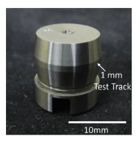
The testing aimed to quantify if the carburization process would affect the rate at which cracks containing local white etching areas (WEAs) manifest within bearing steel. This was accomplished by applying a previously developed set of benchtop test conditions in conjunction with a WEC-accelerating lubricant to steel samples consisting of two different microstructures. (See studies here and here.) The components examined for WECs were 12 mm-diameter bearing rollers (see Figure 3). Ten rollers consisting of through-hardened AISI 52100 steel and 10 consisting of carburized AISI 3310 steel were fabricated for the study.
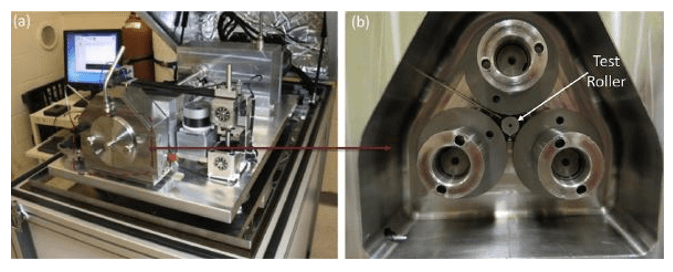
Samples from each set were tested using a PCS Instruments micro-pitting rig (MPR; see Figure 2), which contains a three-ring-on-roller contact used to simulate rolling/sliding between a bearing roller and raceway. Each bearing roller has a 1 mm-wide test track that contacts each of the rigs’ three 54 mm-diameter rings. This test rig and lubricant (a semi-synthetic, VG 68, fully formulated gear oil) have been used in multiple studies examining the formation of WECs. These studies found that the load, lubrication condition, lubricant formulation, stress profile, test duration, and magnitude and direction of sliding affect the formation of WECs.
All tests were conducted using identical parameters: 500N load, -30% slide-to-roll ratio (SRR), 3.4 m/s rolling speed, and 100 degrees C, resulting in a maximum subsurface shear stress of 1.9 GPa at 125 μm.
Results
As recorded in Table 1, a total of 10 tests were performed, with Tests 1–8 conducted under identical conditions in order to investigate whether material composition and heat treatment affect the formation of WECs. Tests 9 and 10 were conducted after analysis was performed on Tests 1–8, the objective being to study the initiation point of WECs within both steels.
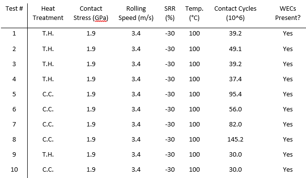
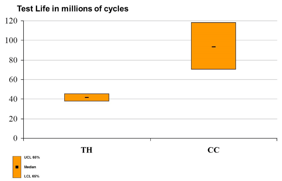
Roller test life is presented in Table 2, where the data clearly illustrates that the carburized AISI 3310 samples outperformed the through-hardened AISI 52100 samples in terms of number of contact cycles until macro-pit formation. However, it is unclear from these tests if the AISI 3310 steel prolonged the time to crack initiation, the rate of crack propagation, or both.
Tests 9 and 10 were conducted to understand the point of crack initiation for both steels. In these tests, samples were metallographically examined at 30 million contact cycles, well before the formation of a surface pit. While WECs were observed in both Tests 9 and 10, no conclusions could be drawn as to the point of initiation for either material.
However, if it is assumed that the rollers from both tests would fail close to the documented average for each steel set (94.65 million cycles for AISI 3310 and 41.23 million cycles for AISI 52100), then it can be stated with great confidence that the AISI 3310 steel significantly impedes the rate of crack propagation within rollers. This is likely due to compressive residual stress induced by the carburized microstructure (presumably the main contributor to the longer observed life).
Conclusions
Under the presented conditions, testing concluded that carburized steel samples lasted, on average, approximately 2.3 times longer than through-hardened samples before resulting in the formation of a macro-pit. It is hypothesized that the increase in test time was due to the combination of the inherent compressive stress and increased toughness within the samples, resulting from the carburization process.
Tests were also conducted to determine when WECs initiated in both steels, though no significant difference in time-to-crack initiation could be identified. This suggests that the increase in time until macro-pit formation in the carburized samples was largely due to prolonging the damage propagation stage. This can again be attributed to the significant compressive residual stress induced by the carburization process.
A Case for Carburized Bearings
For nearly two decades, we have studied the impact of different alloys, coatings and surface treatments on critical wind turbine components, including bearings. Extensive testing and development continue today, with a constant focus on new technologies and approaches for eliminating the costly, unexpected repairs that continue to impact wind operations worldwide.
Compared to through-hardened bearings, carburized bearings can better resist WECs and should be a consideration for any turbine owner who has experienced premature gearbox bearing failures due to this highly damaging condition.
Scott Hyde, Ph.D., is general manager and senior scientist for materials engineering at The Timken Co., an Ohio-based manufacturer of bearings and mechanical power transmission products.


